
Anadigm Field Programmable Analog Array (FPAA)
I recently got an Anadigm Field Programmable Analog Array (FPAA) development
kit. The FPAA is a chip containing switched-capacitor analog circuits that can be
reconfigured to implement many different functions (filters, amplifiers, etc).
The development kit part number is AN221D04, for the AN221E04 chip.
This page is describes my progress in setting up and using the development kit.
The Anadigm Designer 2 software runs under Windows, but I typically use Linux
as my development environment. I use Win4Lin from
Netraverse to run Windows 98 on top
of Linux. The software runs fine in on my system. I can design and test
circuits and download them to the AN221D04 via the serial port with no
problems so far.
 My first project with it is a data acquisition system for in-house use.
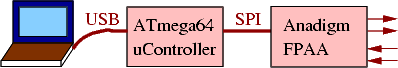
My goal is to implement a USB-based data acquisition system. The FPAA will provide
filtering, level translation and A/D conversion, while an Atmel ATmega64 AVR micro
handles the data transfer to the PC.
My first project with it is a data acquisition system for in-house use.
My goal is to implement a USB-based data acquisition system. The FPAA will provide
filtering, level translation and A/D conversion, while an Atmel ATmega64 AVR micro
handles the data transfer to the PC.
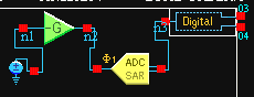 The first step is to acheive data transfer from the FPAA to the AVR. For this
step, I set up an A/D converter with a variable DC input using the Anadigm
Designer2 software (available from the Anadigm website). It uses 3 of the
predefined modules: an A/D, a DC source, and a variable-gain amplifier. The
output is 3 signals: data, clock(4MHz) and sync(250kHz).
The first step is to acheive data transfer from the FPAA to the AVR. For this
step, I set up an A/D converter with a variable DC input using the Anadigm
Designer2 software (available from the Anadigm website). It uses 3 of the
predefined modules: an A/D, a DC source, and a variable-gain amplifier. The
output is 3 signals: data, clock(4MHz) and sync(250kHz).
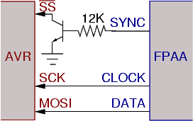 The A/D output is connected to the SPI port of the AVR. The select input of
the SPI port is active low, so the sync output needs to be inverted. A logic
gate could be used, but a simple one-transistor inverter works fine here. I
used a 2N4401, but any high speed switching transistor should work. The
internal pullup resistor of the AVR SS input needs to be enabled for this to work.
The A/D output is connected to the SPI port of the AVR. The select input of
the SPI port is active low, so the sync output needs to be inverted. A logic
gate could be used, but a simple one-transistor inverter works fine here. I
used a 2N4401, but any high speed switching transistor should work. The
internal pullup resistor of the AVR SS input needs to be enabled for this to work.
The maximum recommended clock rate of the A/D module is 4 MHz, which is also
the maximum recommended clock rate of the SPI port when the AVR is running
at 16 MHz.
 Next issue is getting the data into the PC. The data goes out the serial port of
the AVR to an FTDI FT232BM USB-to-serial
converter. The serial interface is being clocked at 2 megabits per second
(the FT232BM supports a 3MHz rate, but 2MHz is the max the AVR ATMega64 UART
can support in asynchronous mode). The receiving PC is running Linux (2.4.22
kernel). Using the standard FTDI driver in the kernel, the best rate so far
is about 1MHz. So, we can stream continuous data at about a 100kHz sampling
rate. The other operating option is to sample at the A/D's maximum 250kHz
sampling rate, buffer the data in the ATmega64's internal SRAM, and then transfer
it to the PC non-real-time. The ATmega64 has 2k of internal SRAM; it also
supports external SRAM, but I don't currently have that on my test board.
Next issue is getting the data into the PC. The data goes out the serial port of
the AVR to an FTDI FT232BM USB-to-serial
converter. The serial interface is being clocked at 2 megabits per second
(the FT232BM supports a 3MHz rate, but 2MHz is the max the AVR ATMega64 UART
can support in asynchronous mode). The receiving PC is running Linux (2.4.22
kernel). Using the standard FTDI driver in the kernel, the best rate so far
is about 1MHz. So, we can stream continuous data at about a 100kHz sampling
rate. The other operating option is to sample at the A/D's maximum 250kHz
sampling rate, buffer the data in the ATmega64's internal SRAM, and then transfer
it to the PC non-real-time. The ATmega64 has 2k of internal SRAM; it also
supports external SRAM, but I don't currently have that on my test board.
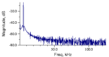 Here's the sample output. It's input signal is an Anadigm sinewave generator
module connected directly to the input of the A/D via an internal on-chip
connection. The input signal is 5kHz
at 2 volts amplitude. Frequency analysis uses a single 1024-point FFT with
a Hamming window.
Here's the sample output. It's input signal is an Anadigm sinewave generator
module connected directly to the input of the A/D via an internal on-chip
connection. The input signal is 5kHz
at 2 volts amplitude. Frequency analysis uses a single 1024-point FFT with
a Hamming window.
Credits: the Linux Penguin logo is from
Simon Budig, www.home.unix-ag.org/simon/
$Date: 2016/02/16 12:29:04 $